Introduction


Welcome to Blending with Forbes! I am assuming that you are familiar with Blender if you found your way here, and are probably trying to work out some problems with modelling.

When I first started blending, I found some of the concepts difficult to learn. Materials and textures gave me fits! Node editing made my machine crash! Anything beyond basic drawing was out of the question. I was frustrated! But I found some tutorials that helped me out of the messes and taught me enough to advance on my own. Then I thought, "wouldn't it be nice if all of this stuff was covered in a single linear tutorial?"

I find I learn best by doing, and that is what I want to do here - teach by doing. Blender can be difficult to learn because of it's somewhat fragmented and hot-key based interface. Once you get a concept though, it makes fairly good sense, and after you've done something two or three times it will become natural.

This will not be a basic tutorial. There are many wonderful basic blender tutorials available to get you up and running. This tutorial is meant to highlight some of the more advanced features of blender in a way that makes sense to the newbie or intermediate user.

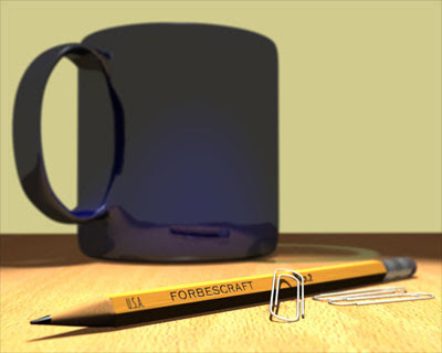
We will concentrate on the scene pictured above from beginning to rendered animation and will cover the following topics:
  • Lighting
  • Materials and textures
  • Advance editing principles
  • Unwrapping UVs
  • Node-based materials
  • Rendering tips
  • Composite rendering
  • Using the game engine to simulate physics
  • Rendering and animation rendering
When you are through with the tutorial you will be able to take many of the techniques you will learn and use them in you own projects. There will be plenty of illustrations along the way.

As I develop the lesson I will include a hot-linked index in this blog to allow you to easily return to a topic when you need a refresher. Let me know what you think and if I need to get into further detail on any particular topic.

Though I have a background in AutoCAD, and have been using Blender for only about six months, I have found it to be a reasonably intuitive and extremely powerful CG tool. Without further ado, I give you Blending with Forbes!

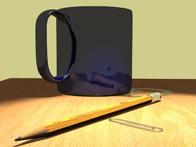
Lesson 13: Node Compositing: Depth of Field

Rearrange your Desktop

Let's move a few things around to get ready for our composite render. From the top (Numpad7) move things to look like this:
Try and get the camera located so your view is close to this (I am using a 50 MM lens on mine):

Changing Our Focus

In order to simulate depth of field in Blender, we need to establish a focal distance. Just as with a real camera, objects that fall within the depth of field area will be in sharp focus while those closer or father away will be blurred. We need to tell our camera where the focal distance is. We need an object to focus on.

We do this with an empty object. In Object Mode, add an empty (Add>Empty). Scale the empty up a bit.a In the Link and Materials tab, change the name in the 'OB:' box to 'FOCUS'. Move the empty to near where the label appears on the pencil. We want our label to be readable:
Now we need to tell our camera which object to focus on. In Object Mode, select the camera. In the Camera tab, in the box labeled 'DofOb:', type 'FOCUS'. Now our camera knows where our depth of field lies.

Compositing Nodes

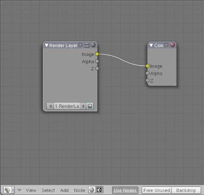
Split the editing window and make one of the split a Node Editing window. A the bottom of the new window is a button with a face icon on it. Click it and then click the Use Nodes button. A Render Layer node and a Composite Node appear:
TIP:
At this point you can save yourself a lot of time by selecting the Scene button and in the Format tab, click the button labeled 'Preview'.

Press F12 to render your scene and select '1 RenderLayer' in the Render Layer Node (I grabbed the bottom right corner of the Composite Node and expanded it):
Now we'll add a Defocus Node (Add>Filter>Defocus). Place it between the other two nodes. Connect the Render Layer Image and Z outputs to the Defocus Image and Z inputs. Connect the Defocus Node Image output to the Composite Node Image input:
As shown above, deselect the 'No zbuffer' button and set the fStop to 1.20. Select the Scene button and in the Anim tab, select the 'Do Composite' button. Render your scene:
That's kind of cool, I guess, but the blurred parts are horribly fuzzy looking!Let's fix that. In the Defocus Node you will find a button labeled 'Preview'. De-select it and render again:
Whoa... now that looks like the real thing! Notice that the tip of the pencil and the eraser are out of focus while the label area is perfectly sharp. We can tweak the look of our rendered image using some of the other settings in the defocus node. We can set the depth of the area of focus by adjusting the fStop number. The larger the number, the deeper the area that is in focus. To demonstrate, change the fStop to 2.5 and re-render:
Now the depth of the sharp area of the camera range encompasses the entire pencil, while the cup is blurred. We can also force the blur to become stronger by using the Maxblur setting. Set the fStop to 1.20 again and set Maxblur to 20. The result:
Finally set the Maxblur back to 0. Let do a full-size, high quality render to we can see how our image is shaping up. Select the Scene button. In the Render tab, under the OSA button, click the button labeled 16. In the Format tab, click the 'FULL' button. Render your scene (this WILL be slow):

Lesson 12: Path Extrusion: A Paperclip

Throwing You a Curve

It may look like the paperclips are the hardest objects to model in the image. It's not true! They are actually very easy to model. We do it with a path extrusion. Start with your scene in top view(Numpad7) and toggle to global view (Numpad/).

In Object mode, add a path (Add>Curve>Path). Tab into Edit Mode. Here is your path:
Select the vertice on the far right and press 'e' to extrude. While pressing the Ctrl key, extrude the path half way between the major grid lines:
Extrude the path again and then again to round the bend:
Keep extruding until you got the rough shape you are looking for:
Now pull a few vertices around to get a more refined shape:
Now tab into Object Mode and drag your curve close to your pencil. Scale it to a realistic size:
Tab back into edit mode, select the vertice shown below, and Shift + 's' and Cursor to selection:
Down to the Wire

Tab back into Object Mode and add a Bezier circle at the cursor (Add>Curve>Bezier Circle). This circle will represent the size of the wire on your paperclip, so scale it appropriately:
With the circle still selected, select the Editing button. In the Link and Materials tab, in the box labeled 'OB:', change the objectname to 'CLIPMESH'. Now select the curve. In the Curve and Surface tab, in the box marked 'BevOb:', enter 'CLIPMESH'. Here's what should happen:

Hmmm... my wire looks a little thick. Easily fixed, though. I just re-select the Bezier circle and scale it:

Now that looks like a paperclip! All I have to do is add material. With the paperclip selected, select the Shading and Material buttons. In the Links and Pipeline tab, select 'SILVER' as the material. Done! Check out the render:

Lesson 11: Advanced Editing - Finishing the Pencil

Finishing Touches

Let's make the pencil model look a little more realistic. In Object Mode, select the pencil and Numpad/ to switch into local view. Tab into edit mode and select the end edgeloop at the tip end of the shaft:
Extrude it about 1/2 the distance of the wood tip, like so:
Select the top face and select the Editing button. In the Link and Materials tab, use the material spinner and select the material to 'YELLOW'. Click the assign button:

Press 'a' and then select the newest edge loop (Shift + Alt + select). Scale the new edge loop down:
Press 'a' to deselect all and select the edge loop forming the wooden tip near where it joins the shaft. Scale it down slightly so it looks like this:
Numpad3 to the side view and select and select the faces of the new cone. The easiest method is to go into face select mode and press 'b' twice to select the faces. Press Shift + 'e' and crease the subsurf to sharpen the edges.
Now I want to sharpen up the tip a little bit. Select the center vertice of the tip and pull it out a little:
Now we will add a little inconstancy to the way our sharpener made the point. Select the two vertices shown and drag them toward the tip:
Go around the tip and randomly pull pairs of vertices forward or back. Do a test render:

Lesson 10: More Nodes: The Pencil Label

Look for the Union Label

Now we are going to use nodes once again. To get started, split the Editing window and change one side to a UV/Imaging window (See Lesson 6).

Numpad7 to the top view and make sure your are not in perspective view (Numpad5 to toggle). Select the pencil and tab to edit mode. Select the top face of the pencil shaft and press 'u' to unwrap it and select 'Project from View' from the menu. A yellow box will appear over the grid in your UV window. Press 's' and scale it up until it fills the grid from top to bottom:
Select Image>New in the UV window to create a new map image. Even though our box is showing as a yellow outline in Blender, the image is blank. If we save the image now, it will be blank and we will have no way to know where our lettering should go when we open it in image editing software to add text. Blender provides a way to create a 2D image from a 3D image called Baking render meshes. We are going to do some baking, baby!

Baking Render Meshes

The process of mesh baking is easy to do and hard to understand. Since we have a surface unwrapped and an image to bake to, let's bake. From the 'Render' menu, choose 'Bake Render Meshes>Texture Only'. When blender is done working, it will have rendered your texture in the box in the UV window! Now we know where to put our text on our image:
How to Use a Baked Image

Now you can do an 'Image>Save as' and save this image outside Blender. From there you can do editing in any image editor that supports layers (Photoshop, GIMP, etc.) and add your label text. When you are finished with your image it should be white text over a black background. Kind of like on real baking shows, in the next section I am going to pull a 'finished cake' out of another oven.

Mapping the Label Image with Nodes

In the previous section we discussed baking and exporting an image to use as a map. Here is the map I came up with using that method (If you want to use it, click it and open the full size image and save that):
To use my image (or your own for that matter) in the UV Window, click Image>Open and browse to the image you want to use. I will appear under your yellow box. Scoot the box around until it fits well:
Nodes Again

No we can move on to our nodes. With same face selected, go select the Editor button and in the Links and Materials tab add a new material. Click the 'Assign' button.

Select to the Shading and Materials buttons. Rename the material 'PENCILMAP'. In the texture tab, clear all textures. Now click 'Add New' in the Texture tab and name the new texture 'PENCILMAP'.

Select the Texture button (leopard skin). Select image as the texture type and load the image of your label map.

Select the Materials button. In the Map Input tab, select the UV button.

Now we are going to edit the nodes. change the UV window to a Node Editor window. In the Links and Pipeline tab, click the 'Nodes' button. The node editor will show a Material and an Output node.

Set the Material Node material to 'YELLOW'. Press Shift + 'd' to duplicate the node. Set this new material node to material 'SILVER'. Here's how it should look:
Now add a Mix node (Add>Color>Mix). Connect the color outputs of the Material Nodes to the color inputs of the Mix node. Connect the color output of the Mix Node to the color input of the Output Node, like so:
Now add a Texture node (Add>Input>Texture). Select 'PENCILMAP' as the texture. Connect the color output to the Fac input on the Mix node:
Now add a Geometry node (Add>Input>Geometry). Connect the UV output to the Vector input of the Texture Node:
I can tell by looking at the Output Node preview that the materials are reversed, so swap the color inputs to the mix node. Also connect the Normal output of the Texture Node to the Normal input of the SILVER Material node:
Let's give her a render and see how she looks:

Lesson 9: Physics Part 1

Set it Up

So now we have a very nice looking pencil that is levitating above the table. We could fool around rotating it and trying to move it to sit on the table, but let's not! Let's let Blender's physics engine set it on the table for us!

First, select your pencil object (it should be a single object if you did the last step of the last lesson). Now select the Logic button:
Change the settings as shown here:
Let's expain this. We press the 'Actor' button to tell the object to interact with other objects within the model. We change the object from static to rigid body to make it subject to gravity. We identify the bounds and ask Blender to use a Convex Hull to identify the bounds of the object when it interacts with other objects. If all of this means nothing, that's OK. We'll do more of this later on. Right now, we just want our pencil on the table.

If you go to the side view (Numpad3) and tab into edit mode, you will notice a dotted circle near the tip of the pencil. This represents the center of gravity for the object:
Press 'a' to select all of your pencil and move it to center on the dotted circle (see the pink dot):
Let it Fall

Ok, we got it ready to go. Want to watch your pencil fall and rock back and forth on the desktop? Press 'p'.

Pretty impressive, huh? Except that when we escape out of the animation our pencil is floating again, right? Let's fix that.

Go to the Game menu and choose Game>Record Games Physics to IPO. Split the window and make 1/2 of it an IPO window. Press 'p' again. When the pencil stops rocking, press the escape key.

Now the action we've just seen is recorded as an animation in our model. The curves in the IPO editor are showing motion in the X, Y, and Z axis. If we right click and drag our mouse in the IPO curve editor we can make the pencil move up and down.

Depending on how high your pencil was above your desk, at about frame 350 the IPO curve should stop. Right-click at the frame where the IPO lines become colored again. Press 'a' to select all IPO curves and press Delete. Confirm delete all. Now our pencil is sitting right on the desk! And it's not going to move until we tell it to.

Lesson 8: More Materials: The Pencil

Make it a Colored Pencil

Now that we have a good pencil shape, we need to start applying some materials. We'll start with the tip. If you don't remember how to assign materials, refer to Lesson 2. If you need help with multiple materials, see Lesson 7. Select all the parts of your pencil and the camera and press Numpad/ to get to the local view.

In Object Mode, select the tip of the pencil. We will our 'BEECH' material for the basis of the the wood part of the pencil, like so:
  1. Select the Shading and Materials buttons
  2. In the Links and Pipeline tab, click the drop down button next to the 'Add New' button and select the material 'BEECH'
  3. Select the Editing button
  4. In the Link and Materials tab, click the 'New' button to create a copy of the 'BEECH' material. Blender names the new material 'BEECH.001'. Click the 'Assign' button
  5. Select the Shading and Materials buttons
  6. In the Texture tab, select the second 'BEECHTEX' texture and click the 'Clear' button to remove it
  7. Click the remaining 'BEECHTEX' texture
  8. In the Map Input tab, select the tube button
  9. Change sizeX, sizeY and sizeZ to 1.00
  10. In the Shaders tab:
  • Spec. = 0
  • Hard. = 1
  • Set the X,Y,Z mapping as follows (this rotates the texture 90 degrees):
Press F12 and render to check the material:
Now tab to Edit Mode and select the vertices that represent the graphite. Select the Editing button and add and assign a new material to your pencil tip. Select the Shading and Materials buttons and rename your material 'GRAPHITE'. Clear the 'BEECHTEX' textures and change the following settings in the Shaders tab:
  1. Spec. = .8
  2. Hard. = 115
Now in the Material tab, change the Col to black (000000). Render to see the result:
Oh man, that's some big lead! Here's how to fix it. Cut another edge loop in the wood part and while it's still pink, slide it toward the tip. You'll see the lead getting shorter:
Render again. Oh yeah, that's more like it!
Now let's move to the ferrule. Tab into Object mode and select the ferrule. Select the Shading and Materials buttons and click the 'Add New' button. Name the new material 'SILVER'. In the Material tab, change the Col to white (FFFFFF). Go to the Shaders tab and change the following settings:
  1. Ref. (Reflectance) = .31
  2. Spec. = .5
  3. Hard. = 25
Now on the Mirror Trans tab, change the following settings:
  1. Select the 'Ray Mirror' button
  2. RayMir. = .85
  3. Fac. = 1.31
  4. Aniso = .496
Render to check the look:
Since the material has nothing to reflect but the background color, it looks rather washed out. If you press Numpad/ and turn on the other objects, you get a better idea of how it will look eventually (the reflectance really slows this render down):

Now select the eraser and create a new material called 'ERASER'. In the Material tab, change the Col to a nice pink (FCD0D0). Now go to the Shaders tab and change the following:
  1. Ref. = .79
  2. Spec. = 0
  3. Hard. = 511
Do a check render (I switched back to local view to save render time):
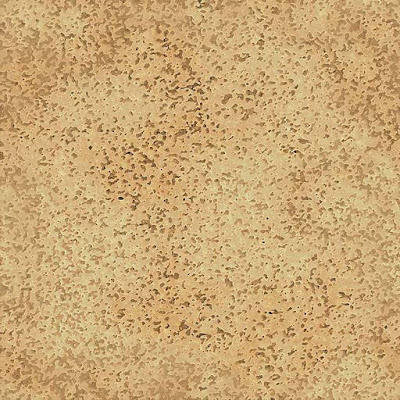
Now for the shaft material. Select the shaft and create a new material called 'YELLOW'. Set the color (Col) to FF9F34. We need a little texture here. I used a cork image for the texture. Here it is...
In the Texture tab, add a new texture and name it 'DENTS'. Select the Texture button and select 'Image' as the Texture Type. Load the cork image you downloaded. Select the Material button and go to the Map Input tab. Change the following settings:
  1. Select the 'Sphe' (Spherical) button
  2. Set sizeX, sizeY, and sizeZ to .20
Now in the Map To tab, change the following settings:
  1. Deselect the Col button
  2. Select the Nor button
  3. Set the Normal slider to .75
Now render out the scene. Looks good!
All Together Now

Now that we have all of the materials applied to the various parts, let's join the pencil into one object. Select all the parts and choose Objects>Join Objects (or Ctrl 'j') and join them all together. In order for the pencil shaft to remain hexagonal, we need to select the faces of the shaft and crease the subsurf (Shift + 'e' and drag the mouse). Now our pencil is one object. In our next lesson we use Blender physics to set the pencil on the desktop!