Showing posts with label Materials. Show all posts

Lesson 10: More Nodes: The Pencil Label

Look for the Union Label

Now we are going to use nodes once again. To get started, split the Editing window and change one side to a UV/Imaging window (See Lesson 6).

Numpad7 to the top view and make sure your are not in perspective view (Numpad5 to toggle). Select the pencil and tab to edit mode. Select the top face of the pencil shaft and press 'u' to unwrap it and select 'Project from View' from the menu. A yellow box will appear over the grid in your UV window. Press 's' and scale it up until it fills the grid from top to bottom:
Select Image>New in the UV window to create a new map image. Even though our box is showing as a yellow outline in Blender, the image is blank. If we save the image now, it will be blank and we will have no way to know where our lettering should go when we open it in image editing software to add text. Blender provides a way to create a 2D image from a 3D image called Baking render meshes. We are going to do some baking, baby!

Baking Render Meshes

The process of mesh baking is easy to do and hard to understand. Since we have a surface unwrapped and an image to bake to, let's bake. From the 'Render' menu, choose 'Bake Render Meshes>Texture Only'. When blender is done working, it will have rendered your texture in the box in the UV window! Now we know where to put our text on our image:
How to Use a Baked Image

Now you can do an 'Image>Save as' and save this image outside Blender. From there you can do editing in any image editor that supports layers (Photoshop, GIMP, etc.) and add your label text. When you are finished with your image it should be white text over a black background. Kind of like on real baking shows, in the next section I am going to pull a 'finished cake' out of another oven.

Mapping the Label Image with Nodes

In the previous section we discussed baking and exporting an image to use as a map. Here is the map I came up with using that method (If you want to use it, click it and open the full size image and save that):
To use my image (or your own for that matter) in the UV Window, click Image>Open and browse to the image you want to use. I will appear under your yellow box. Scoot the box around until it fits well:
Nodes Again

No we can move on to our nodes. With same face selected, go select the Editor button and in the Links and Materials tab add a new material. Click the 'Assign' button.

Select to the Shading and Materials buttons. Rename the material 'PENCILMAP'. In the texture tab, clear all textures. Now click 'Add New' in the Texture tab and name the new texture 'PENCILMAP'.

Select the Texture button (leopard skin). Select image as the texture type and load the image of your label map.

Select the Materials button. In the Map Input tab, select the UV button.

Now we are going to edit the nodes. change the UV window to a Node Editor window. In the Links and Pipeline tab, click the 'Nodes' button. The node editor will show a Material and an Output node.

Set the Material Node material to 'YELLOW'. Press Shift + 'd' to duplicate the node. Set this new material node to material 'SILVER'. Here's how it should look:
Now add a Mix node (Add>Color>Mix). Connect the color outputs of the Material Nodes to the color inputs of the Mix node. Connect the color output of the Mix Node to the color input of the Output Node, like so:
Now add a Texture node (Add>Input>Texture). Select 'PENCILMAP' as the texture. Connect the color output to the Fac input on the Mix node:
Now add a Geometry node (Add>Input>Geometry). Connect the UV output to the Vector input of the Texture Node:
I can tell by looking at the Output Node preview that the materials are reversed, so swap the color inputs to the mix node. Also connect the Normal output of the Texture Node to the Normal input of the SILVER Material node:
Let's give her a render and see how she looks:

Lesson 8: More Materials: The Pencil

Make it a Colored Pencil

Now that we have a good pencil shape, we need to start applying some materials. We'll start with the tip. If you don't remember how to assign materials, refer to Lesson 2. If you need help with multiple materials, see Lesson 7. Select all the parts of your pencil and the camera and press Numpad/ to get to the local view.

In Object Mode, select the tip of the pencil. We will our 'BEECH' material for the basis of the the wood part of the pencil, like so:
  1. Select the Shading and Materials buttons
  2. In the Links and Pipeline tab, click the drop down button next to the 'Add New' button and select the material 'BEECH'
  3. Select the Editing button
  4. In the Link and Materials tab, click the 'New' button to create a copy of the 'BEECH' material. Blender names the new material 'BEECH.001'. Click the 'Assign' button
  5. Select the Shading and Materials buttons
  6. In the Texture tab, select the second 'BEECHTEX' texture and click the 'Clear' button to remove it
  7. Click the remaining 'BEECHTEX' texture
  8. In the Map Input tab, select the tube button
  9. Change sizeX, sizeY and sizeZ to 1.00
  10. In the Shaders tab:
  • Spec. = 0
  • Hard. = 1
  • Set the X,Y,Z mapping as follows (this rotates the texture 90 degrees):
Press F12 and render to check the material:
Now tab to Edit Mode and select the vertices that represent the graphite. Select the Editing button and add and assign a new material to your pencil tip. Select the Shading and Materials buttons and rename your material 'GRAPHITE'. Clear the 'BEECHTEX' textures and change the following settings in the Shaders tab:
  1. Spec. = .8
  2. Hard. = 115
Now in the Material tab, change the Col to black (000000). Render to see the result:
Oh man, that's some big lead! Here's how to fix it. Cut another edge loop in the wood part and while it's still pink, slide it toward the tip. You'll see the lead getting shorter:
Render again. Oh yeah, that's more like it!
Now let's move to the ferrule. Tab into Object mode and select the ferrule. Select the Shading and Materials buttons and click the 'Add New' button. Name the new material 'SILVER'. In the Material tab, change the Col to white (FFFFFF). Go to the Shaders tab and change the following settings:
  1. Ref. (Reflectance) = .31
  2. Spec. = .5
  3. Hard. = 25
Now on the Mirror Trans tab, change the following settings:
  1. Select the 'Ray Mirror' button
  2. RayMir. = .85
  3. Fac. = 1.31
  4. Aniso = .496
Render to check the look:
Since the material has nothing to reflect but the background color, it looks rather washed out. If you press Numpad/ and turn on the other objects, you get a better idea of how it will look eventually (the reflectance really slows this render down):

Now select the eraser and create a new material called 'ERASER'. In the Material tab, change the Col to a nice pink (FCD0D0). Now go to the Shaders tab and change the following:
  1. Ref. = .79
  2. Spec. = 0
  3. Hard. = 511
Do a check render (I switched back to local view to save render time):
Now for the shaft material. Select the shaft and create a new material called 'YELLOW'. Set the color (Col) to FF9F34. We need a little texture here. I used a cork image for the texture. Here it is...
In the Texture tab, add a new texture and name it 'DENTS'. Select the Texture button and select 'Image' as the Texture Type. Load the cork image you downloaded. Select the Material button and go to the Map Input tab. Change the following settings:
  1. Select the 'Sphe' (Spherical) button
  2. Set sizeX, sizeY, and sizeZ to .20
Now in the Map To tab, change the following settings:
  1. Deselect the Col button
  2. Select the Nor button
  3. Set the Normal slider to .75
Now render out the scene. Looks good!
All Together Now

Now that we have all of the materials applied to the various parts, let's join the pencil into one object. Select all the parts and choose Objects>Join Objects (or Ctrl 'j') and join them all together. In order for the pencil shaft to remain hexagonal, we need to select the faces of the shaft and crease the subsurf (Shift + 'e' and drag the mouse). Now our pencil is one object. In our next lesson we use Blender physics to set the pencil on the desktop!

Lesson 6: Using Material Nodes - The Coffee Ring

A Stain on the Plane

When I was building this scene, I was looking around my desk for inspiration. The coffee cup is, of course, ubiquitous. And what respectable desk doesn't have a coffee ring? It just so happens that the coffee ring is a perfect lesson in material node editing.

Multiple Materials

Each object can have more than one material assigned to it. Right now, the plane that represents our desktop has the material "BEECH" assigned to it. We are about to assign a second material that represents coffee spills. Again, if you need a refresher in basic material assignment and texturing, see Lesson 2 in this series.

Let's assign a second material to our desktop plane. Select the desktop in object mode and follow these steps:
  1. Click the Editing button
  2. In the links and materials tab, click the new material button (highlighted below):
  3. You will notice that the material spinner above the new button now reads "2 Mat 2". This means that the object references two materials. Blender automatically named the new material "BEECH.001"
Now click on the Shaders and then the Materials buttons:
In the Link to Object tab, rename the new material "COFFEE". In the Texture tab, select each of the copies of "BEECH" and click the clear button. Now that our material doesn't look like beech wood anymore, let's try and make it look like coffee. Follow these steps:
  1. In the Materials tab, click the topmost color bar and set the color to Hex 4F3D11, brown.
  2. In the Shaders tab: Spec. = 1.2; Hard = 511
  3. In the Mirror Trans tab click the Ray Mirror button and set: RayMir = .35; Gloss=1
  4. Click the Ray Transp button and set: IOR:1.3
  5. Back in the Materials tab set the A (Alpha) slider to .790
We now have a brown, transparent, reflective material which will simulate coffee. To assign this material to the desktop and see how it looks, follow these steps:
  1. Click the Editing button:
  2. Press tab to enter Edit Mode.
  3. In the Link and Materials tab, press the Assign button (highlighted below):
Press F12 and we find our cup floating on a puddle of coffee (with cream I would say)!


Creating a Node Map Using the UV Editor

Now we have two materials associated with our desktop - beech wood and wet coffee. What we need is a way to tell the plane which parts are covered with beech and which parts are covered with coffee. That's where nodes come in.

The first thing we need to do is create a map that tells the coffee where we want it to be. I want there to be a coffee ring partially under the cup, so I have to find a way to make that happen. UV Unwrapping comes to the rescue!

To begin the UV Unwrap, we need to split the editing screen in half. Hover your mouse at the top of the editing window, just below the menu bar, until the cursor changes to an up-down arrow. Right-click and choose Split Area from the pop-up menu. Drag the new window to about 1/2 the width of the editing window. In the bottom left-hand corner of the new window, click the drop-down button and select UV/Image Editor. Your screen should look like this:


With the desktop plane selected, tab into edit mode. Press 'u', and select Unwrap from the menu. You will notice that the grid in the UV Editor window will be enclosed by a yellow box. The space within the grid represents the face of our plane! So what?

Now we need to make an image to place the map on. In the menu bar at the bottom of the UV Editing window, click on Image>New. For what we are doing, the default image size is OK, so just click OK. You will notice that you can no longer see the grid in the UV Editor - that's because it is covered by the image we just created.

Now we need to see in our model in real-time the changes we are making in the image editor. We need to be able to see where we are putting our coffee ring. Go to the viewport shading button and select textured:
Now you will notice that the desktop has turned black as well. That is because it is using the image in the UV Editor as a texture! Now we will use the built in image editor to help us locate the coffee ring on the desk. Near the bottom right corner of the image editing window is a button with a pencil icon on it called "Enable image painting" - click it. In the image editor window, click the View>Paint Tool. You are ready to start painting your desktop.

Start drawing circles using the brush tool in the Image Painter. Keep drawing circles until you get one in the spot you want, offset from the cup a little bit. You may have to keep trying for a little bit until you get it where you want it. Here's what it looked like when I tried it:
Once you get a circle roughly the right size and location, switch the brush function from 'Mix' to 'Subtract' and erase the circles you don't want. You now have two choices; you can either try to do the image editing in Blender, or select Image>Save as and save the image to be edited in an external editor. I saved the image and opened it in Photoshop, created a new layer and drew a more accurate circle in the correct location and saved the image again. Here's what mine looked like in the image editor after I reloaded it:
If you did your editing internal to blender, be sure to do an Image>Save as to save your image. We are now done with the UV Editor window, so we can close it up. You can also change the viewport shading back to solid (leaving it in textured mode slows down the redraws).

Assigning Our Image Map as a Material

This is going to get a bit rough, so hang with me here. Nodes are one of the hardest things to understand in Blender, but also one of the most powerful features.

As you will remember, we have two materials assigned to our desktop, and we are about to add a third. The third one will be the image map we just made. Here we go...

In Object Mode, with the plane selected, click the Editor button again to get to the Link and Materials tab. As we did before, click the new button for materials in Link and Materials and another material will be added to your plane ('3 Mat 3'). Once again click the Materials and then the Shaders buttons. Change the name of the material to 'COFFEEMAP' or something like that.

Go to the Texture tab and click Add New. Type a name like 'COFFEEIMGMAP' and click the Texture button (leopard skin). Select 'Image' from the Texture Type drop-down and in the Image tab, click 'Load' and browse to the map image we made in the previous section.

Click the Material Button again and in the Map Input tab, change sizeX, sizeY and sizeZ to 1. At the top of the box select the button labeled UV. Finally go back to the Editor button, tab into Edit Mode, select the new material (3 Mat 3) and assign it to the plane.

Let me briefly describe what we have done. We added another material to the plane and made the texture for that material the map image we just completed. We scaled it 1 to 1 and told Blender that the texture is to be mapped to the surface (UV). Finally we assigned it as the texture for the plane. Did you get all that? After you do it two or three times you will be able to remember.

Bring on the Nodes

Now that we have all of our materials assigned to the plane, we can start editing the nodes. To do so, we need to once again split the screen (or change the UV Editor window) and select the Node Editor window as our second window.

TIP:

To make connection between nodes, left-click on the output nodule you want to connect and with the mouse button down, drag the connection to the input nodule you want to connect to. To erase a connect, left-click near the connection you want to erase and drag a window over it. Release the mouse button and it will disappear.

With the desktop plane selected, click the Shaders and then the Materials buttons. To the right of the material name (which should be 'COFFEEMAP') is a button called Nodes - click it. The Node Editor comes to life with two nodes - a material node and an output node:
Click the material node and use the drop down to select the 'BEECH' material. Now press Shift + 'd' to duplicate it and drag it to the side. Change the material type in this second node to 'COFFEE'. It should look something like this:
Now we need to add a mix node. With your mouse over the Node Editor window, right-click and select Add>Color>Mix. Place the mix node between the material nodes and the output node. From the yellow color output of each Material node, drag a connection to the two color inputs of the Mix node. Form the yellow color output of the Mix Node, drag a connection to the color input of the Output Node. The nodes should now look like this:

Now right-click the Node Editor window once again and select Add>Input>Texture. Place the Texture Node to the left of the Material Nodes. Select the 'COFFEEMAP' texture in the drop- down. Drag a connection from the yellow color output of the Texture Node to the Fac Input Node of the Mix Node, like so:

Lastly, right-click in the Node Editor window one more time and select Add>Input>Geometry. Place the Geometry Node to the left of the Texture Node. Drag a connection from the UV output of the Geometry Node to the Vector input of the Texture Node. Your finished nodes should look like this:

Now press F12 to render your scene. If you find that your materials are mapped in reverse, meaning that the desktop looks like coffee with wood stains on it, simply swap the color inputs on the Mix Node. Your rendering should look something like this:

Viewed from another angle, it looks like this:

Now you have a rudimentary understanding of material nodes. Don't be afraid to play with things until you get it to look just the way you want it. Experimentation will lead to all kinds of discovery! In our next lesson, we will make the pencil.

Lesson 5: Subsurfing and Shiny Stuff

Make it Smooth

Now that our cup is built, we need to get it to where it doesn't look so 'blocky'. We do this by subsurfacing it (referred to as subsurfing in Blender).

TIP:

Subsurfing is highly demanding at render time. The subsurf creates hundreds of facets on each face of the model, making it look smooth. The more levels of subsurfing we use on an object at render time, the longer it takes to render the object. Try and keep the subsurf to the absolute minimum render level that looks good in your render. Adding more levels will not significantly improve the outcome but will slow the render way down. One exception is with reflective materials like we will be modelling here in which case the reflectance will make the sub-surfed facets create 'jagged' reflections.

To subsurf our cup, select it in object mode and go to the edit buttons:
In the Modifiers tab, click the Add Modifier button and select Subsurf from the list. Change the following settings:
  1. Set Levels to 4
  2. Set Render Levels to 5 (this is a high number - see the tip above)
Now press F12 and we see that our cup is looking considerably more 'cupish':


All That Glitters is Not Gold

Now we will give our cup a high gloss ceramic texture. I'm not going to cover every step of the material creation because I did that in Lesson 2. If you need a refresher, go back and look at that tutorial.

Add a new material for the cup and set a color in the Material tab by clicking the color bar next to the Col button. I set the color to Hex 000253, dark blue. Make these changes to the settings in the Shaders tab:
  1. Spec. = 1.6
  2. Hard = 278
Now we do something different! We are going to make our material reflective like a mirror. Click the Mirror Trans tab next to the Shaders tab. Select the Ray Mirror button and set:
  1. RAYMIR slider to .25
  2. Gloss to 1.00
Since we have changed the color of our cup to a dark color, now would be a good time to change the background of the render so we can see it better when we render it.

Click the Shading and World buttons:
In the World tab, click the upper left color bar and enter the Hex number D0CC8C to change the render background color. Press F12:


Now our cup looks nice and shiny. You could stop here, but if you observe the way a real ceramic cup looks, there are variances in the thickness of the glaze that cause smooth 'ripples in the surface. We will now model these.

Go to the texture tab and create a new texture called "MARBLE". Click the Textures button and under Texture Type, select "Marble". In the Marble tab, change the following:
  1. NoiseSize = .250
  2. NoiseDepth = 2
  3. Turbulance=31.22
  4. Nabla = 0.045
Click the material button to return to your material. In the Map Input tab, change:
  1. sizeX, sizeY and sizeZ to .25
  2. Select the button marked Tube.
Click the Map To button and change the following settings:
  1. Deselect the Col button
  2. Select the Nor button
  3. Set the Nor slider to .03
Now we have a cup with a shiny, ripply surface:


Lesson 2: Materials and Textures - The Desktop

It's All Material

Now for a part of blender that is very confusing when you first start using it - materials. It works really, really well after you get the hang of it, but getting the hang of it takes a little time.

The first thing we must do is set up a material for our desktop. Take the following steps:
  1. Select the plane that represents the desktop
  2. Click the Shading and Materials buttons
  3. In the Links and Pipeline tab, click the Add New button
  4. Give your material a name like "BEECH"
  5. In the Shaders tab, change the following settings:
  • Spec. (Specularity - the amount of shininess) to 0.6
  • Hard. (the hardness of the material) to 200
You must always create a material first and then assign the material texture. The texture is just an attribute of the material.

Add Some Texture

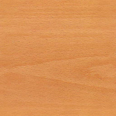
One way to establish a texture is by using an image. We want our desktop to look like beech wood, so we need to find an image of beech wood. To find textures, I generally do a Google search with the term "Seamless Texture" and then narrow the search to images. In this case, you would search for "Seamless Texture Beech Wood" or something similar to that. Here is the image I used (right-click and 'Save image as..' to download):


This texture image is not actually seamless, but it doesn't matter since our desktop is all one face.

To use this texture on our desktop, we need to associate it with our material. In the texture tab (usually on the right in the Shader buttons) click the button that says 'Add New'. In the box that appears, type "BEECHTEX" or something similar. This is the name of your texture.

Now we need to assign the texture type. To do so, we need to get to the texture buttons and load our image:
  1. Click the Shading and Textures buttons:
  2. In the texture tab, select 'Image' from the Texture Type drop-down
  3. In the Image tab, click the button that says 'Load' and browse to the beechwood image you downloaded above. Your texture will now show in the preview window
  4. Return to the Materials buttons:
  5. In the Map Input tab next to the Texture tab, change sizex, sizey and sizez to a value of 3.0. This is where you scale your texture - the smaller the number the larger the scaling.
TIP:
To set a the camera angle quickly, pan and zoom to the view you want and press Ctrl+Alt+Numpad0. To return to the camera view, press Numpad0. When in camera view you can adjust the view by selecting the camera view outline (the solid rectangle around the camera view) and:
  1. Press 'g' and move the mouse to pan
  2. Press 'g', click the center mouse wheel and move the mouse to zoom the camera in and out
  3. Press 'r' to rotate the camera
Go ahead and hit the F12 key now and render your desktop. It should look a little like this:


Add Some Texture to Your Texture

You have now got a texture based on an image, but it looks rather flat. We need to use a normal map to make it have personality. A normal map makes a 2-dimensional image appear 3-dimensional. Return to the Texture tab and follow these steps:
  1. Just below the button on the left that says "BEECHTEX", click the empty texture button
  2. Use the drop-down button to the left of the "Clear" button to select "BEECHTEX" once more. You now have the image texture "BEECHTEX" referenced twice by your material
  3. Click the original "BEECHTEX" button and then click the up arrow symbol above the Clear button (note the two buttons highlighted below):
  4. Now click on your new "BEECHTEX" texture and click the button with the down arrow on it. Steps 3 & 4 copy your texture mappings (like the scaling we set earlier) from one texture to another. You now have to identical textures on the same material
  5. Click the Map To tab
  6. Change the following settings:
  • Clear the Col (Color) button
  • Highlight the Nor (Normal) button
  • Highlight the Ne (Negative) button
  • Set the Nor (Normal) slider to 2
TIP:

What in the world do all of these settings do? The color button (Col) tells the material to derive color (or an image in the case of an image texture) from the texture. The intensity of the color is controlled by the Col (Color) slider. The Normal button (Nor) tells the material to derive it's normal (3D) mapping from the texture. Since light colors are typically mapped as high points in normal maps, we use the Negative (Ne) button to produce a negative of the image to use as the normal map, making the darker parts look lower.
To get a better idea of what the normal map does, crank the normal slider up to 25 and press F12 to render the scene. You should be able to see all kinds of little bumps on the surface. We only need it set to 2 so it picks up little highlights in the scene - we don't want it to look like old barn wood!

You have now completed a material using an image map for both color and normal mappings. Press F12 again and render your scene!