Let's move a few things around to get ready for our composite render. From the top (Numpad7) move things to look like this:
 Try and get the camera located so your view is close to this (I am using a 50 MM lens on mine):
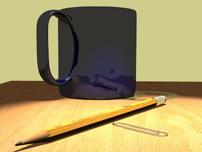
 Try and get the camera located so your view is close to this (I am using a 50 MM lens on mine):
Changing Our Focus
In order to simulate depth of field in Blender, we need to establish a focal distance. Just as with a real camera, objects that fall within the depth of field area will be in sharp focus while those closer or father away will be blurred. We need to tell our camera where the focal distance is. We need an object to focus on.
We do this with an empty object. In Object Mode, add an empty (Add>Empty). Scale the empty up a bit.a In the Link and Materials tab, change the name in the 'OB:' box to 'FOCUS'. Move the empty to near where the label appears on the pencil. We want our label to be readable:
 Now we need to tell our camera which object to focus on. In Object Mode, select the camera. In the Camera tab, in the box labeled 'DofOb:', type 'FOCUS'. Now our camera knows where our depth of field lies.
 Now we need to tell our camera which object to focus on. In Object Mode, select the camera. In the Camera tab, in the box labeled 'DofOb:', type 'FOCUS'. Now our camera knows where our depth of field lies.
Compositing Nodes
Split the editing window and make one of the split a Node Editing window. A the bottom of the new window is a button with a face icon on it. Click it and then click the Use Nodes button. A Render Layer node and a Composite Node appear:
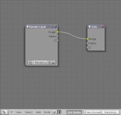

TIP:At this point you can save yourself a lot of time by selecting the Scene button and in the Format tab, click the button labeled 'Preview'.
Press F12 to render your scene and select '1 RenderLayer' in the Render Layer Node (I grabbed the bottom right corner of the Composite Node and expanded it):
 Now we'll add a Defocus Node (Add>Filter>Defocus). Place it between the other two nodes. Connect the Render Layer Image and Z outputs to the Defocus Image and Z inputs. Connect the Defocus Node Image output to the Composite Node Image input:
 As shown above, deselect the 'No zbuffer' button and set the fStop to 1.20. Select the Scene button and in the Anim tab, select the 'Do Composite' button. Render your scene:
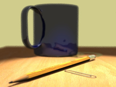 That's kind of cool, I guess, but the blurred parts are horribly fuzzy looking!Let's fix that. In the Defocus Node you will find a button labeled 'Preview'. De-select it and render again:
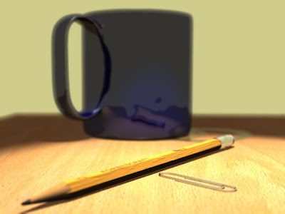 Whoa... now that looks like the real thing! Notice that the tip of the pencil and the eraser are out of focus while the label area is perfectly sharp. We can tweak the look of our rendered image using some of the other settings in the defocus node. We can set the depth of the area of focus by adjusting the fStop number. The larger the number, the deeper the area that is in focus. To demonstrate, change the fStop to 2.5 and re-render:
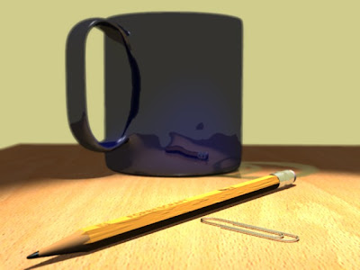 Now the depth of the sharp area of the camera range encompasses the entire pencil, while the cup is blurred. We can also force the blur to become stronger by using the Maxblur setting. Set the fStop to 1.20 again and set Maxblur to 20. The result:
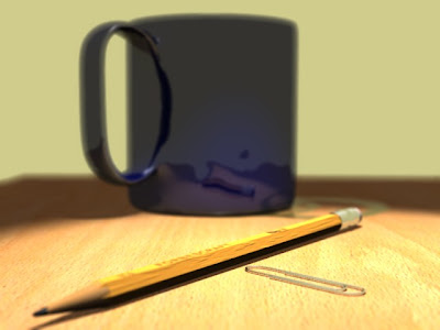 Finally set the Maxblur back to 0. Let do a full-size, high quality render to we can see how our image is shaping up. Select the Scene button. In the Render tab, under the OSA button, click the button labeled 16. In the Format tab, click the 'FULL' button. Render your scene (this WILL be slow):
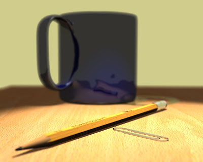
 Now we'll add a Defocus Node (Add>Filter>Defocus). Place it between the other two nodes. Connect the Render Layer Image and Z outputs to the Defocus Image and Z inputs. Connect the Defocus Node Image output to the Composite Node Image input:
 As shown above, deselect the 'No zbuffer' button and set the fStop to 1.20. Select the Scene button and in the Anim tab, select the 'Do Composite' button. Render your scene:
 That's kind of cool, I guess, but the blurred parts are horribly fuzzy looking!Let's fix that. In the Defocus Node you will find a button labeled 'Preview'. De-select it and render again:
 Whoa... now that looks like the real thing! Notice that the tip of the pencil and the eraser are out of focus while the label area is perfectly sharp. We can tweak the look of our rendered image using some of the other settings in the defocus node. We can set the depth of the area of focus by adjusting the fStop number. The larger the number, the deeper the area that is in focus. To demonstrate, change the fStop to 2.5 and re-render:
 Now the depth of the sharp area of the camera range encompasses the entire pencil, while the cup is blurred. We can also force the blur to become stronger by using the Maxblur setting. Set the fStop to 1.20 again and set Maxblur to 20. The result:
 Finally set the Maxblur back to 0. Let do a full-size, high quality render to we can see how our image is shaping up. Select the Scene button. In the Render tab, under the OSA button, click the button labeled 16. In the Format tab, click the 'FULL' button. Render your scene (this WILL be slow):


 Posts
Posts